
Building the layout
The layout is the set of physical keys — their position, size and rotation — plus the matrix that says how each key is wired electrically. Both feed the firmware export and both live under keyboard in the config.
Create the geometry
The left panel's Build from section has four entry points. The Design a keyboard dialog offers the same starting points, plus Import config and Load from saved builds.
| Tool | Dialog | What it does |
|---|---|---|
| Presets | "Start from a preset — replaces the current board layout" | Pick a known layout (Corne, ortho, 60%, numpad, macropad…). |
| Import KLE | "Import from KLE — keyboard-layout-editor.com raw data" | Paste the Raw data from KLE's Download menu → Import layout. |
| Make grid | "Make a grid — Ortholinear rows × columns" | Set Rows / Columns → Create R×C grid. |
| Add key | — | Drop a single 1U key onto the canvas. |
The first three replace the geometry (layer names kept, bindings reset to pass-through); Add key is additive.
Presets
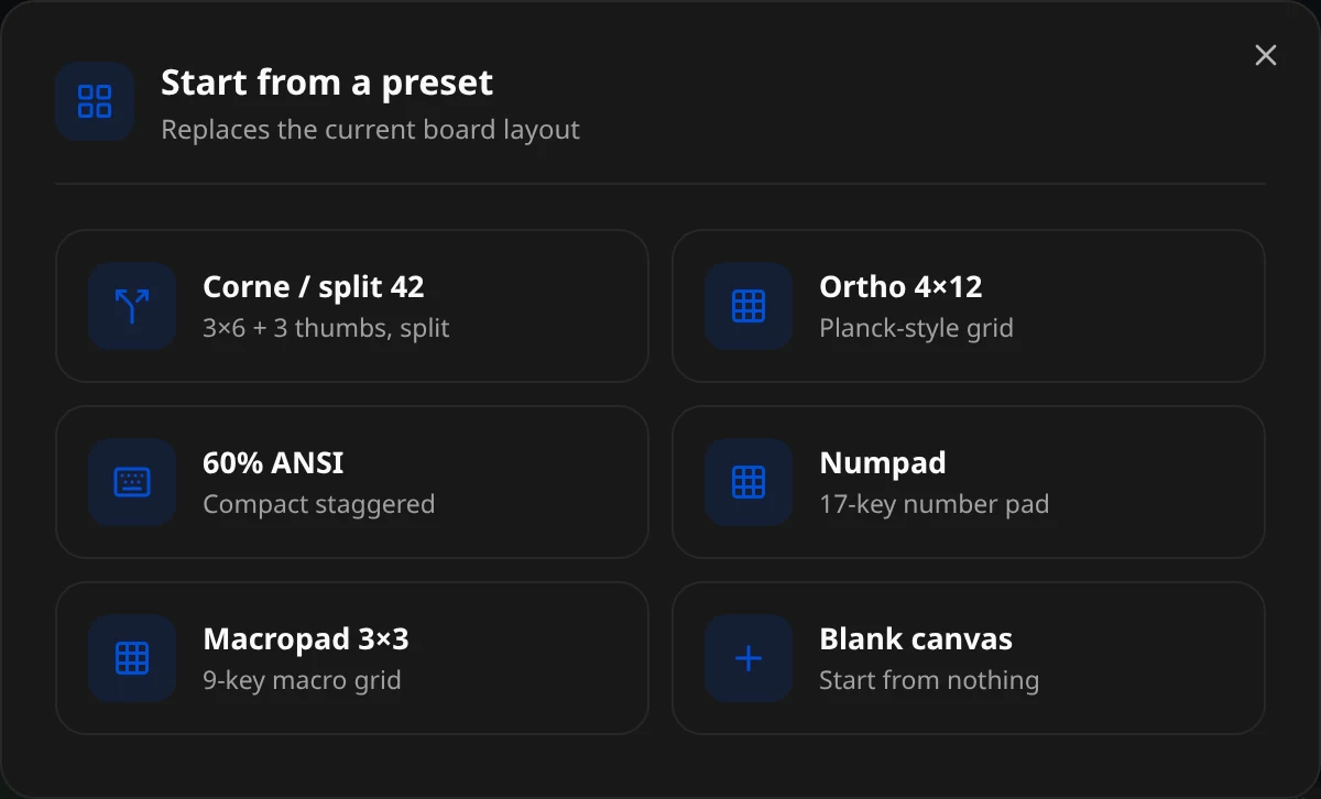
"Start from a preset — Replaces the current board layout":
| Preset | What you get |
|---|---|
| Corne / split 42 | 3×6 + 3 thumbs, split |
| Ortho 4×12 | Planck-style grid |
| 60% ANSI | Compact staggered |
| Numpad | 17-key number pad |
| Macropad 3×3 | 9-key macro grid |
| Blank canvas | Start from nothing |
Import from KLE
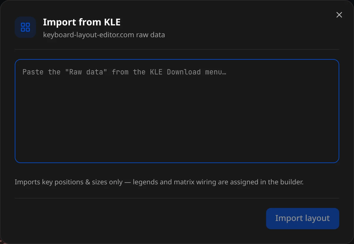
On keyboard-layout-editor.com, open Raw data, copy everything, paste it into the box ("Paste the 'Raw data' from the KLE Download menu…") and press Import layout.
Make a grid
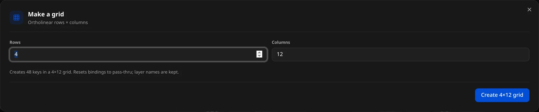
"Make a grid — Ortholinear rows × columns": set Rows and Columns, then Create R×C grid. "Creates R×C keys in a R×C grid. Resets bindings to pass-thru; layer names are kept."
KLE imports
"Imports key positions & sizes only — legends and matrix wiring are assigned in the builder." So after a KLE import, wire the matrix and assign bindings here.
Position keys on the canvas
- Drag a key to move it; selected keys move together.
- Marquee — drag on empty canvas to box-select;
Cmd/Ctrl + Aselects all. - Arrow keys nudge 0.25U (hold Shift for 1U).
Cmd/Ctrl + Dduplicates;Delete/Backspaceremoves.- Undo/Redo covers every geometry edit.
Snapping
The toolbar snap mode switches Snap to grid ⟷ Free form; the snapping toggle enables ⅛U snapping while dragging/resizing (status bar shows snap ⅛U / snap off / free-form).
What a key looks like in the config
Each key is a CanonGeometry. A plain 1U key is just its position — defaulted w/h/r are omitted:
{ "x": 3, "y": 1 }A wider, rotated, matrix-wired thumb key carries the extra fields:
{
    "x": 3.5,
    "y": 3.2,
    "w": 1.5,
    "r": 15,
    "rx": 3.5,
    "ry": 3.2,
    "matrix": [3, 5]
}| Field | Inspector label | Meaning |
|---|---|---|
x, y | X / Y | Position in key units (U). |
w, h | Width / Height | Size in U (default 1). |
r | Angle ° | Rotation. |
rx, ry | Pivot X / Pivot Y | Rotation origin. |
matrix | Row / Column | Electrical position [row, col]. |
pin | Direct GPIO pin | Per-key direct GPIO (direct-pin boards). |
element | Key / Encoder / Slider | Input element type. |
The inspector edits all of these — see Key inspector.
Wire the matrix
Firmware needs the electrical row and column of each key. Two ways to set it:
Matrix-wiring overlay (toolbar Matrix wiring view) — draws each row and column as a line through its keys, labels every key with its
row.col, and puts an editable pin chip at the end of each line ("Click to set the GPIO pin"); add rows/cols with the + buttons (Add a matrix row / Add a matrix column).
Per key, in the inspector's Matrix wiring · row / column section.
The Identity panel's Matrix section sets the dimensions and has an Auto button — "Auto assigns each key's row/column from its position":
"keyboard": {
  "matrix": { "rows": 4, "cols": 12, "diodeDirection": "col2row", "mode": "matrix" },
  "pins":   { "rows": ["GP4","GP5","GP6","GP7"], "cols": ["GP8","GP9","…"] }
}- When a key's
matrixis set, it is authoritative. - When absent, the compiler derives it from physical position.
Matrix vs geometry
Physical position is not electrical wiring. For a board you intend to flash, set the real [row, col] per key (or supply a kscan + transform) and re-check the generated map before flashing.